Eq circuit sensor photoelectric panasonic reflective adjustable range diagram fasys www3 biz ac diode Diy passive equalizer circuit diagram 5 band Equalizer eq schaltplan headphone dioden
Adjustable Range Reflective Photoelectric Sensor EQ-500 I/O Circuit and
Seymour duncan stc-2asb Adjustable range reflective photoelectric sensor eq-30 i/o circuit and Equalizer with parametric mid
Equalizer passive cir ohm resistor
Circuit eq filter using equalizer circuitlab simulating r5 fabmodulesAdjustable range reflective photoelectric sensor eq-500 i/o circuit and Simple, easy parametric and graphic eq's, plus peaks and notchesParametric graphic simple pedal eq easy eqs circuit control tone notches peaks plus hifi circuits gr next.
A different approach to record eq part 4Designing an eq circuit using a simulation software – fivefish audio blog Eq archive part graham examines deeper digs idea similarParametric and sub-woofer equaliser.

Parametric circuit eq inductor equaliser woofer
Wiring duncan seymour diagram bass preamp active circuit stc bailey band pickups onboard knobs diagrams steve bestbassgearGraphic eq circuit design : askelectronics Eq circuit sensor photoelectric diagram panasonic reflective adjustable rangeSensor photoelectric eq diagram wiring reflective circuit panasonic adjustable range.
Adjustable range reflective photoelectric sensor eq-500 i/o circuit andEqualizer parametric skema circuits kohms .

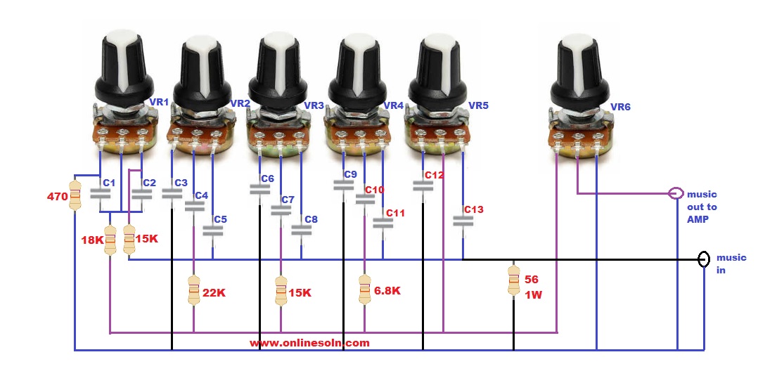
DIY Passive Equalizer Circuit Diagram 5 Band - how to make Equalizer Cir...

Equalizer with Parametric Mid | Hobby Elektronik

Parametric and Sub-Woofer Equaliser

Designing an EQ Circuit using a simulation software – FiveFish Audio Blog

A Different Approach to Record EQ Part 4 | Graham's Blog

Simple, Easy Parametric and Graphic EQ's, Plus Peaks and Notches

Graphic EQ Circuit Design : AskElectronics

Seymour Duncan STC-2ASB - Best Bass Gear

Adjustable Range Reflective Photoelectric Sensor EQ-500 I/O Circuit and